a view into the material
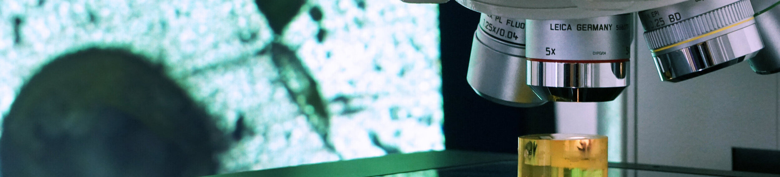
Imaging methods
Imaging techniques are the basis for understanding the behavior of a component under load. Its properties are primarily influenced by the existing structure of the plastics. This results from the material used, additives and the actual processing conditions. Imaging techniques provide a view into the material or the component. At the KUZ, various imaging techniques are available. They yield important information on a component, which can be used for everything from material development to failure analysis.
- Optical 3D metrology

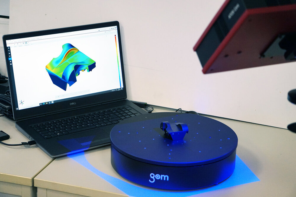
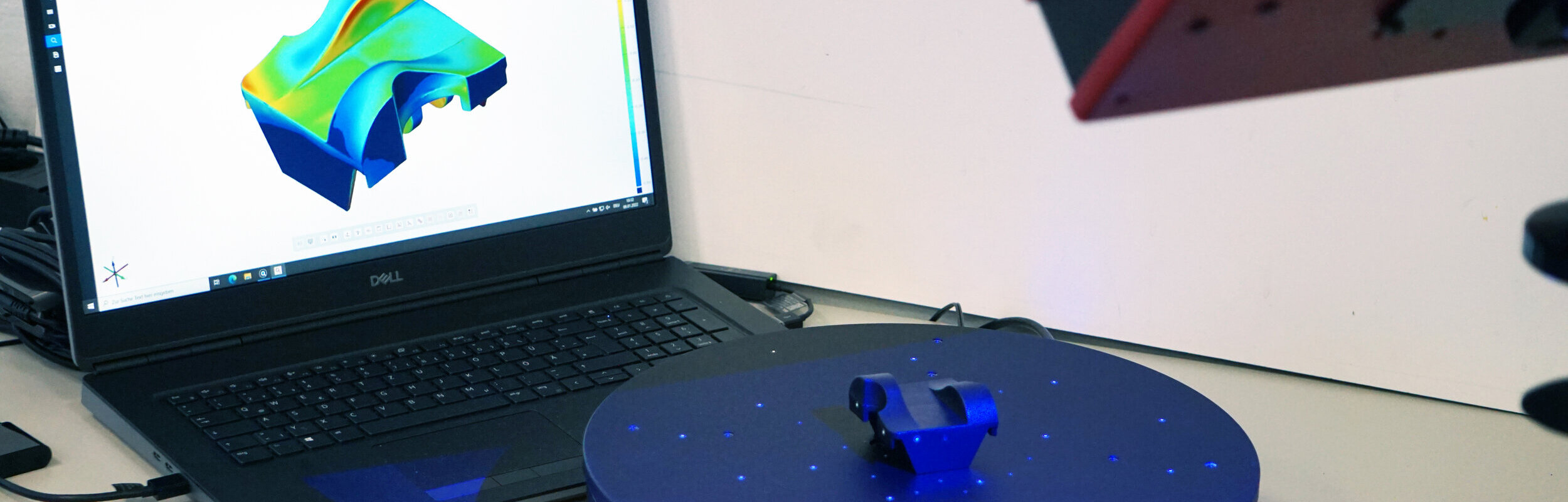
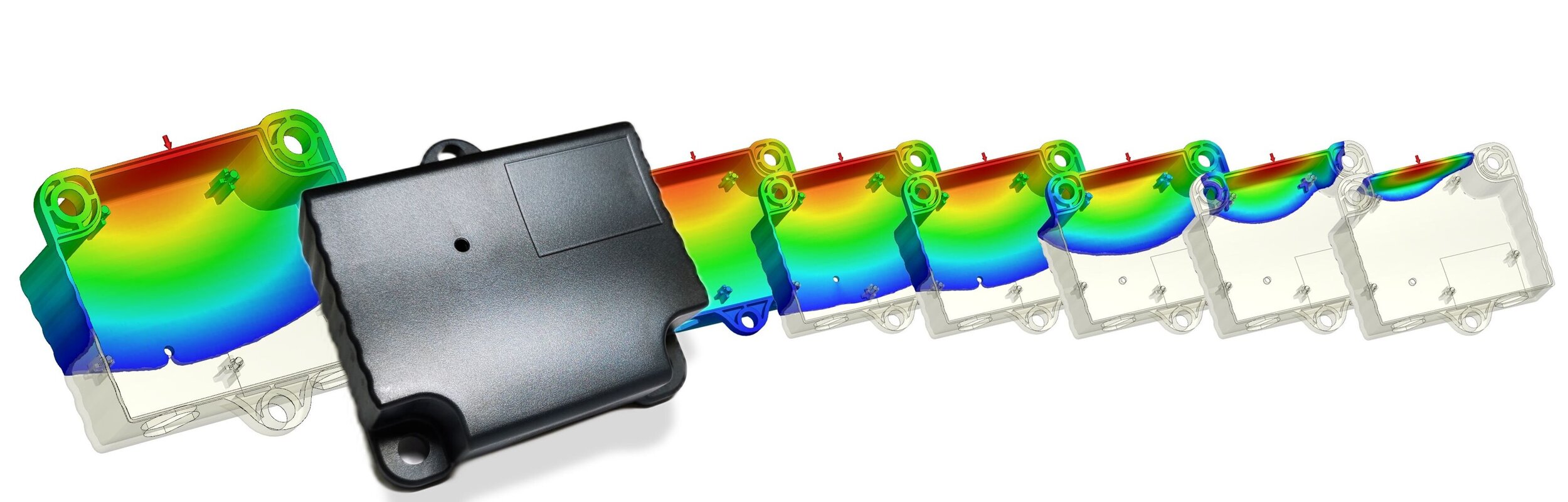
The innovative 3D coordinate measuring technique is an optical measuring method. At the KUZ, for example, ATOS sensors and Aramis sensors from Carl Zeiss GOM Meteorolgy are available. The devices are used to detect, for example, dimensional changes in the component due to external influences. This allows target/actual comparisons to be illustrated via color-coded deviation displays.
Similarly, complex components can be digitized without contact, for example for processing in a CAD system or subsequent 3D printing. Using the GOM Aramis system, it is also possible to quantify stresses and strains of a component under mechanical or climatic load in a non-contact and non-destructive manner via gray value correlation.
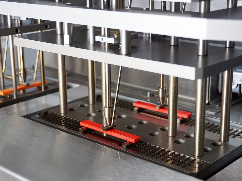
These special and component tests can be used to examine the behavior of a component under load as well as to clarify, re-enact and document damage mechanisms. Due to the interdisciplinary setup of the KUZ Leipzig, individual test setups can be realized quickly.
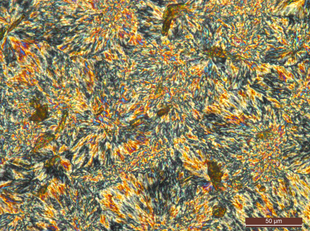
- Light microscopy
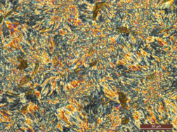
In an examination using optical microscopy, as the name implies, light is used for imaging. In optical microscopes, lenses, apertures and filters are used to adjust different illumination situations. These include incident light microscopy and transmitted light microscopy, for example. Different contrast methods are used to achieve optimal imaging results. Several light microscopes of different types are in use at the KUZ in order to be able to examine a large number of different samples.
Methods of light microscopy:
- Bright field microscopy: This is the classical method of light microscopy, where light is shone through the specimen and a bright background appears.
- Dark-field microscopy: This uses indirect illumination to produce images with a dark background.
- Polarization microscopy: Polarization filters can be used to achieve additional contrast in order to make the invisible visible. This can be used, for example, to detect residual stresses in transparent molded parts.
- Differential interference contrast: This method can be used to create images which convert differences in the optical path length in the object under observation into differences in the brightness of the image. In reflected light, this causes changes in the surface morphology to become visible.
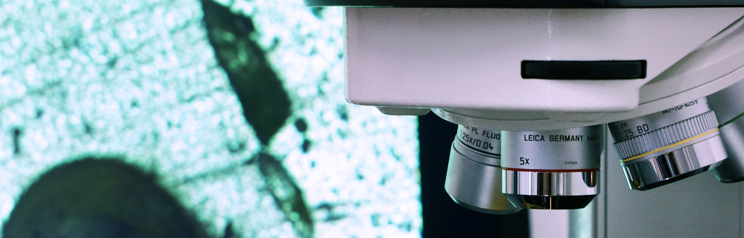
- Scanning electron microscopy (SEM)
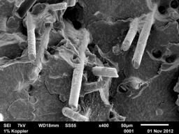
Scanning electron microscopy (SEM) generates the images by means of an electron beam that is passed over the object to be magnified. The interactions of the electrons with the surface being examined can be detected and imaging information obtained from the various signals. Signal types include secondary electron contrast, which mainly represents the topography of the object. Backscattered electron contrast depends primarily on the average atomic number of the material and produces a material contrast image. Also the characteristic X-ray radiation, which is produced by knocked out electrons in the material and their recombination, can be evaluated by means of an EDX detector and thus statements can be made about elements present on the sample surface.
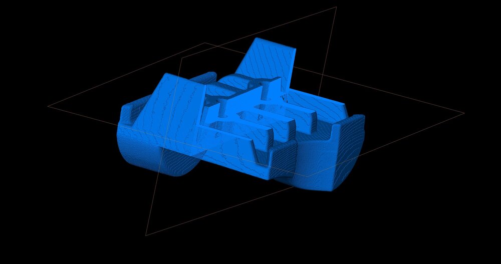
- Computed tomography (CT)

Computed tomography (CT) is a technique that uses X-rays for spatial imaging. The X-rays are used to produce radiographic images on a detector. The object under examination is rotated in front of the detector until a sufficient number of radiographic images are available to calculate a three-dimensional volume. With these reconstructed data, statements can be made about the internal structure and internal or external geometries of the examined sample. In addition, it is possible to gain information about different materials and the once generated point cloud (STL file) can act as a starting point for further investigations, e.g. for the assessment of dimensional stability or fiber ornamentation.

Our imaging services in detail
Our equipment at a glance
VHX 500FD
Digital microscope
Keyence
TomoScope XS
Computed tomography
Werth Messtechnik GmbH
EM JSM-6510
Scanning electron microscope with EDX probe (Bruker)
Jeol
DM6000 M
Light microscope
Leica
optical 3D coordinate measuring technology
ATOS Core
Carl Zeiss GOM Metrology GmbH
3D camera system
Aramis
Carl Zeiss GOM Metrology GmbH


 "/>
"/>